About the Author

DannyCounts
I was recently certified by Autodesk as a Civil 3D Implementation Certified Expert or ICE. I have worked in the Civil Engineering industry since 1987. In 1994 I started my consulting business doing training and consulting for Civil Engineering customers utilizing Autodesk civil engineering technology. I started L.A. CAD in 1999 and we are currently the 3rd largest Autodesk partner in the U.S. Studied Civil Engineering at Long Beach State, graduated in 1996.


In The News
Catch up on the latest news and press in the U.S. CAD Press Room.
Links
- L.A. CAD Website
- Autodesk's Civil Community Website
- CAD Digest
- BLAUGI-Civil
- AUGI Civil 3D Forum
- Autodesk C3D Discussion Group
- Civil 3D White Papers (L.A. CAD)
Civil 3D Blogs
- Digging In-Danny Counts of L.A. CAD
- Civil3D.com
- Paving The Way-Scott McEchron
- Beneath The Lines-Jason Hickey
- CAD vs. BIM-Jay Zallan
- The Dan and Dave Show-Dan Philbrick & Dave Simeone
- Wicked Cool Stuff-Anthony Governanti
Previous Posts
- Civil 3D 2009 Side by Side compatibility warning
- Southern California CAD Summit 2008
- Data Shortcut Projects from 2008 to 2009
- U.S. CAD exhibiting Knowledge-Trax at Autodesk Uni...
- Civil 3D Services in Hawaii in new Hawaii office
- Vault Implementation Package for Civil 3D
- Civil 3D and Land Desktop 2008 SP2 almost ready!
- Southern California CAD Summit 2007
- Civil 3D and Land Desktop Knowledge Trax Assessmen...
- Seminar: Civil 3D Label Styles to meet Agency Requ...
Archives
- January 2006
- February 2006
- March 2006
- April 2006
- May 2006
- June 2006
- July 2006
- August 2006
- September 2006
- October 2006
- November 2006
- January 2007
- July 2007
- October 2007
- November 2007
- April 2008
- August 2008
- September 2008
Digging In...
Wednesday, November 22, 2006
3-Line Profiles (revisited) and workflow
Check out the following screen capture of the 3-line profile in the "Profile Base" drawing. It shows station/elevation for grade breaks. The Profile Style being used is a "3-line" style that has been preset to NOT show a profile grid and include a label set that shows station and elevation for all Grade Breaks along with the grades. Many companies store their profile grids in the Sheet Files, so this method assumes that the grid will be in the sheet files.
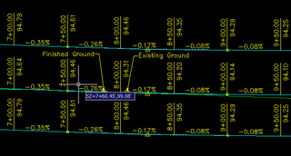
The above drawing exists in the Profile Base (per Vault and Project workflow) and is Externally Referenced into the Sheet files. The Profile View style applied to the profiles suppresses the grid. The 3-line profile shows the Right TC in the bottom view, the FG Centerline along with the EG centerline in the middle view, and in the top view, it shows the Left TC.
The Workflow consists of applying a Profile View Style that incorporates a grid initially, within the Profile Base drawing. Once the 3-line profiles have been created (per a previous post I made)... http://digginginc3d.blogspot.com/2006/10/3-line-profiles-in-civil-3d.html you would move the middle and top profiles down to "compress" the view of the 3 profiles... essentially moving the 3 profiles closer together. When moving them down, you should use object snaps to select points on the grid (of the top two profiles) so you have equal spacing between the 3 profiles. Once you get them close enough to where the annotation is still readable, you would then apply another "preset" profile view style (called "3-line profile view", as an example) to the 3 profiles. This style again would suppress the grid since the grid is contained within the sheet files.
Based upon the screen capture above, you would want to ensure you have created appropriate Civil 3D Label Styles that label the 3-line profile correctly for grade breaks and vertical curves on the finished grade. Although this is a work-around to having a real 3-line profile command in Civil 3D, in the event that we dont see this command soon, this is an acceptable work-around that is quite efficient.
<< Home
![]()