About the Author

DannyCounts
I was recently certified by Autodesk as a Civil 3D Implementation Certified Expert or ICE. I have worked in the Civil Engineering industry since 1987. In 1994 I started my consulting business doing training and consulting for Civil Engineering customers utilizing Autodesk civil engineering technology. I started L.A. CAD in 1999 and we are currently the 3rd largest Autodesk partner in the U.S. Studied Civil Engineering at Long Beach State, graduated in 1996.


In The News
Catch up on the latest news and press in the U.S. CAD Press Room.
Links
- L.A. CAD Website
- Autodesk's Civil Community Website
- CAD Digest
- BLAUGI-Civil
- AUGI Civil 3D Forum
- Autodesk C3D Discussion Group
- Civil 3D White Papers (L.A. CAD)
Civil 3D Blogs
- Digging In-Danny Counts of L.A. CAD
- Civil3D.com
- Paving The Way-Scott McEchron
- Beneath The Lines-Jason Hickey
- CAD vs. BIM-Jay Zallan
- The Dan and Dave Show-Dan Philbrick & Dave Simeone
- Wicked Cool Stuff-Anthony Governanti
Previous Posts
- Civil 3D 2009 Side by Side compatibility warning
- Southern California CAD Summit 2008
- Data Shortcut Projects from 2008 to 2009
- U.S. CAD exhibiting Knowledge-Trax at Autodesk Uni...
- Civil 3D Services in Hawaii in new Hawaii office
- Vault Implementation Package for Civil 3D
- Civil 3D and Land Desktop 2008 SP2 almost ready!
- Southern California CAD Summit 2007
- Civil 3D and Land Desktop Knowledge Trax Assessmen...
- Seminar: Civil 3D Label Styles to meet Agency Requ...
Archives
- January 2006
- February 2006
- March 2006
- April 2006
- May 2006
- June 2006
- July 2006
- August 2006
- September 2006
- October 2006
- November 2006
- January 2007
- July 2007
- October 2007
- November 2007
- April 2008
- August 2008
- September 2008
Digging In...
Friday, October 20, 2006
Dynamic Grading w/ Feature Lines
As you can see by the below screen capture, it is fairly obvious that the back of the lots may be higher than the pad elevations when you look at the contours. The reason for this is the finished floors have not been added yet. The lot to lot slopes are a 2 to 1 slope between the lots which are dictating the surface right now. The lot to lot slopes also are a 1% positive grade from the front to back of lot.
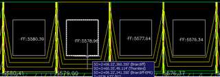
The pads themselves have already been turned from polylines into feature lines. The pad elevations have been automatically assigned by extracting elevations from a surface when the lots were flat (before the 1% grade was applied from front to back). This was done purposefully in order to keep the pads flat. Now we will use the Feature line editing tools to set a logical increment to bump the pads up.
On the Feature Line Toolbar in Civil 3D, we will select the elevation editor followed by picking the far left pad. Once the pad is selected, we will see the Panorama for the Elevation Editor. By selecting the Set Increment button, we can set the increment to 0.5

Then in the elevation Editor, we will use the Raise Inrementally button to raise the pads by 0.5

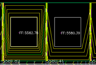
Provided you have your surface for the PADS set to Automatically Rebuild, you will see the contours for the PADS surface automatically re-display as you add the Finished Floor elevations. The labels for the finished floor also update automatically.
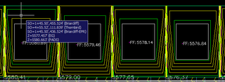
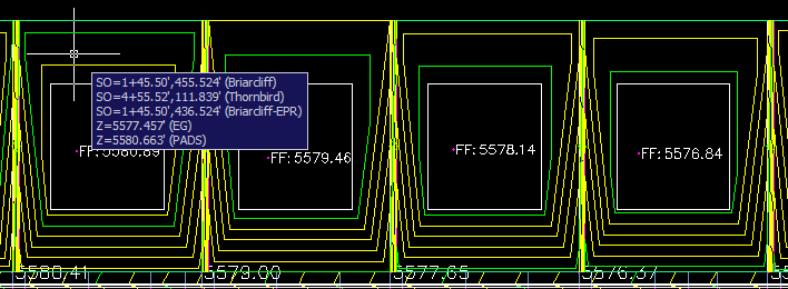
You can use the Select feature line or parcel line tool in the elevation editor to jump to a different pad...

In a matter of a few seconds for these 4 lots, you can incrementally raise the finished floor above the finished ground, and again, the labels update as well...

The pads themselves have already been turned from polylines into feature lines. The pad elevations have been automatically assigned by extracting elevations from a surface when the lots were flat (before the 1% grade was applied from front to back). This was done purposefully in order to keep the pads flat. Now we will use the Feature line editing tools to set a logical increment to bump the pads up.
On the Feature Line Toolbar in Civil 3D, we will select the elevation editor followed by picking the far left pad. Once the pad is selected, we will see the Panorama for the Elevation Editor. By selecting the Set Increment button, we can set the increment to 0.5

Then in the elevation Editor, we will use the Raise Inrementally button to raise the pads by 0.5

Provided you have your surface for the PADS set to Automatically Rebuild, you will see the contours for the PADS surface automatically re-display as you add the Finished Floor elevations. The labels for the finished floor also update automatically.

You can use the Select feature line or parcel line tool in the elevation editor to jump to a different pad...

In a matter of a few seconds for these 4 lots, you can incrementally raise the finished floor above the finished ground, and again, the labels update as well...
<< Home
Wednesday, October 18, 2006
3-Line Profiles in Civil 3D
Making an earlier post on 3-line profiles more clear.
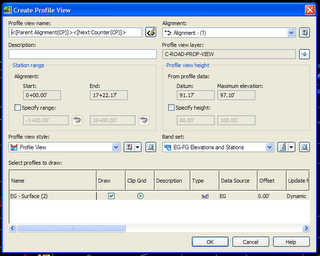
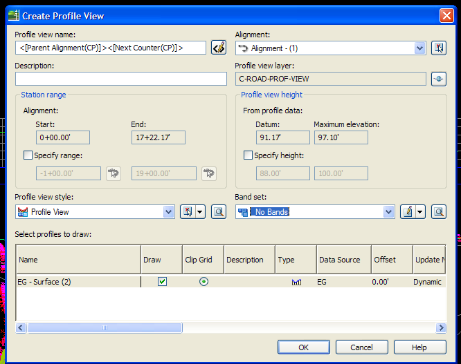
It is very common in Southern California and some other areas in the United States to have 3-line profiles represented on drawing sheets. A 3-line profile generally consists of a profile that shows the existing ground line with the finished ground centerline as well as two other profiles that each show the existing ground along with one of them showing the Left Top of Curb and the other showing the Right Top of Curb.In Civil 3D, there is not a command that will automatically create a 3-line profile, but here is a simple work around...Create your first profile by using ProfilesàCreate from Surface. As normal, add the data and select the Draw Profile View button...
In the Profile View dialog box, you may want to keep bands for the bottom profile view of the 3-line profile.
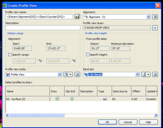
Next, use the ProfilesCreate View command to create the other two profiles. Notice in the below screen capture, that you should consider turning off the bands for two other profiles and make sure to choose the upper left point of the grid of the previous profile view…
Once you create the three profile views, you should check to make sure the style is correct. For instance, you may want to turn off the graph title. This can be done by clicking on any profile view, then right clicking and selecting Edit Profile View Style
Once you have the three profile views with the proper style, you can begin to layout the three finished ground profiles within each of the three views. Use the ProfilesCreate by Layout tool to create your first profile.
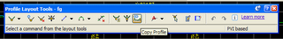
Instead of creating all three profile views with the Create by Layout tool, you could create the last two profiles using the following method. Go to ProfilesEdit Profile Geometry. When prompted to select an FG profile, select any FG profile even though it currently exists in all three profile views, they are all really the same profile. When the following toolbar appears, select the Copy Profile button…
When the Copy Profile Data dialog box appears, ensure the Create new Profile option is selected and hit OK. Do this exact process again, to create a third FG profile.
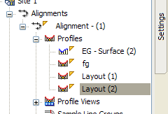
If you look in the prospector, you will see two additional profiles with the name of Layout1 and Layout2. You can rename these profiles by right clicking on them and selecting Properties.
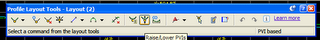
Next, go back to ProfilesEdit Profile Geometry and select any FG profile in any view. Based upon draw order, it will select the Layout1 or Layout2. Once the Profile Edit toolbar appears, choose the Raise or Lower PVI’s button as shown below. Proceed to move up and down the Layout1 and Layout 2 profiles. It is of course very important for you to edit these profiles to ensure the proper design of these profiles.
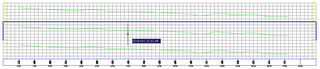
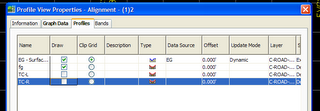
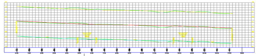
Now that all the profiles are designed, it is time to turn off profiles in other profile views… Right click on one of the profile views and select Profile View Properties. When the dialog appears, select the Profiles tab. You will notice that you can control which profiles appear in this profile view. In the below, we want to see only the EG and FG, not the Top of Curb profiles…
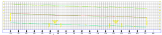
Following this, you will need to highlight then right click on the two other profile views. One would show the EG with the left TOC and the other would show EG with the right TOC. The result might look like the following…
It is very common in Southern California and some other areas in the United States to have 3-line profiles represented on drawing sheets. A 3-line profile generally consists of a profile that shows the existing ground line with the finished ground centerline as well as two other profiles that each show the existing ground along with one of them showing the Left Top of Curb and the other showing the Right Top of Curb.In Civil 3D, there is not a command that will automatically create a 3-line profile, but here is a simple work around...Create your first profile by using ProfilesàCreate from Surface. As normal, add the data and select the Draw Profile View button...
In the Profile View dialog box, you may want to keep bands for the bottom profile view of the 3-line profile.

Next, use the ProfilesCreate View command to create the other two profiles. Notice in the below screen capture, that you should consider turning off the bands for two other profiles and make sure to choose the upper left point of the grid of the previous profile view…
Once you create the three profile views, you should check to make sure the style is correct. For instance, you may want to turn off the graph title. This can be done by clicking on any profile view, then right clicking and selecting Edit Profile View Style

Once you have the three profile views with the proper style, you can begin to layout the three finished ground profiles within each of the three views. Use the ProfilesCreate by Layout tool to create your first profile.
Instead of creating all three profile views with the Create by Layout tool, you could create the last two profiles using the following method. Go to ProfilesEdit Profile Geometry. When prompted to select an FG profile, select any FG profile even though it currently exists in all three profile views, they are all really the same profile. When the following toolbar appears, select the Copy Profile button…

When the Copy Profile Data dialog box appears, ensure the Create new Profile option is selected and hit OK. Do this exact process again, to create a third FG profile.
If you look in the prospector, you will see two additional profiles with the name of Layout1 and Layout2. You can rename these profiles by right clicking on them and selecting Properties.

Next, go back to ProfilesEdit Profile Geometry and select any FG profile in any view. Based upon draw order, it will select the Layout1 or Layout2. Once the Profile Edit toolbar appears, choose the Raise or Lower PVI’s button as shown below. Proceed to move up and down the Layout1 and Layout 2 profiles. It is of course very important for you to edit these profiles to ensure the proper design of these profiles.

Now that all the profiles are designed, it is time to turn off profiles in other profile views… Right click on one of the profile views and select Profile View Properties. When the dialog appears, select the Profiles tab. You will notice that you can control which profiles appear in this profile view. In the below, we want to see only the EG and FG, not the Top of Curb profiles…

Following this, you will need to highlight then right click on the two other profile views. One would show the EG with the left TOC and the other would show EG with the right TOC. The result might look like the following…
<< Home
Monday, October 02, 2006
Vault or Data Shortcuts?
This might help you make a decision based on the latest from the Dave and Dan show...
http://civilcommunity.autodesk.com/blogs/blog/4/blogpost/2900/
http://civilcommunity.autodesk.com/blogs/blog/4/blogpost/2900/
<< Home
![]()